Decanter Centrifuge
The solid-bowl centrifuge now almost universally known as the decanter centrifuge has, indeed, become the workhorse of a wide range of liquid / solid separation activities. Its application to the dewatering of waste sludge’s has made it a most valuable tool in combating environmental pollution. This has made the decanter a well-known and widely appreciated piece of equipment.
The Basic Decanter: Continuous Separation Principle
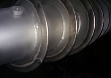
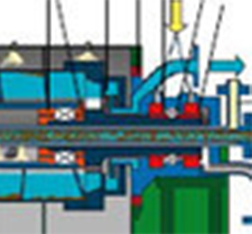
Although a complicated piece of machinery, the decanter centrifuge embodies a simple principle, that of the screw conveyor. In basic terms, the decanter comprises a solid cylindrical bowl, rotating at high speed. Inside the bowl is a scroll (screw conveyor) rotating at a slightly different speed. The differential speed between bowl and scroll provides the conveying motion to collect and remove the solids, which accumulate at the bowl wall.
1. Two Phase Decanter Centrifuge (Decanter)
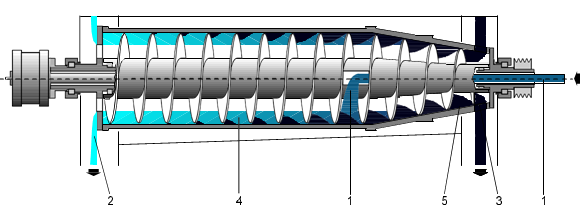
1. Feed 2. Liquid phase 3. Solids phase 4. Pond 5. Dry beach
The solid-bowl scroll-discharge centrifuge now almost universally known as the decanter centrifuge has, indeed, become the workhorse of a wide range of liquid/solid separation activities. Solid bowl centrifuges have been operating according to the same basic principle since the 19th Century. Over the years, new design details for specific separation tasks and the use of resilient, high-quality materials have improved the machine. Above all, electrical components for measuring and control technology increased the performance and availability of the decanter centrifuge.
 The decanter’s hour has come as soon as the solids content in the suspension to be processed is particularly high. These machines provide the benefits of high clarifying efficiency and maximum dewatering as well as the separation of liquids with the simultaneous removal of solids. The main requirements in this respect include a high bowl speed, a powerful drive for the scroll and a scroll speed which automatically adapts to the solids loading in the feed.
Five crucial factors determine the performance of decanter centrifuges:
- Centrifugal force required for sedimentation of the solids
- Clarification area necessary to “capture” the solids
- Differential speed required to transport the solids out of the decanter
- Hydrodynamic design, which determines the exact parameters for the turbulence
- Design of the conveyor and beach sections, which are important for efficient solids transportation.
- All welds are ground to meet specific sanitary finish standards (optional)
- All product wetted parts are provided with a surface finish in accordance with specified surface roughness values
- Spray nozzles are provided for the centrifuge housing and for the interior of the scroll body
- The centrate impeller is adjustable to facilitate the flushing of the bowl
- Frequency-controlled drives for CIP-cleaning at low speed
- Electro-polished scroll, housing and bowl surfaces (optional)
- Sealed construction to control odor emissions and avoid contamination of the product
- Ease of operation with continuous or automatic control systems
- Limited consumables such as filter media or filter aids
Compact Design
The Basic Decanter: Continuous Separation Principle
The Slurry of liquid and suspended solids is fed along the center line, to some fixed position within the bowl, and is accelerated outwards to join the pond of liquid held on the bowl wall by the centrifugal force. This same force then causes the suspended solids to settle, and accumulate at the bowl wall. The clarified liquid then flows along the bowl, to leave at one end of it, over some kind of weir design, which sets the level of the liquid surface in the bowl.
The other end of the bowl is sloped inwards, towards the center, thus providing a beach, up which the solids are conveyed, to be discharged from the bowl, at the top of the beach. Whilst the solids are conveyed up the beach, some, hopefully most, of the entrained liquid drains back into the pond, to join the liquid flow towards the far end.
The scroll usually is carried on a hollow axial hub, through which the slurry feed tube passes to the feed zone. The diameter, the number, and the pitch of the conveyor flights are chosen to match the needs of the slurry being treated as are the depth of the pond, the length of the bowl, the conveyor differential speed, and the angle of slope of the beach.
Most decanters operate with their axis horizontal, in which case they usually are mounted in substantial bearings at each end of the bowl. Vertical operation is possible, in which case the bowl is carried only on one set of bearings, at the top. If the decanter is short, then cantilevered horizontal operation is also possible, with bearings at one end only.
The rotating bowl is enclosed in a casing, which is divided to ensure that the discharged liquid (the "centrate") and solids cannot remix after separation. The basic decanter is completed with a drive motor, usually electrical, and a gearbox, which controls the differential speed of the conveyor.
Modern centrifuges are used in technical processes for the mechanical separation of mixtures of solids and liquids. Sedimentation and filtration are mechanical separation processes, in contrast to distillation, incineration and thermal drying, which are thermal separation processes. In many processes, the mechanical separation has a decisive influence on product quality, production efficiency and environmental impacts. In solid-based applications, decanters ensure optimum separation efficiency, particularly in the case of suspensions with a very high proportion of solids. They are also used for the extraction of constituents from liquids and for concentrating, dewatering and classifying solids. Mechanical separation processes are found in practically all industrial sectors, including but not limited to food, chemical, pharmaceutical, biotech, mineral, and environmental processing.
The following basic process operations are possible using decanter centrifuges:
- Clarifying decanter for clarifying liquids
- Dewatering decanter for maximum concentration of solids
- Concentrating decanter for the concentration of solids
- Separating decanter for the separation of liquid mixtures and the simultaneous separation of solids
- Classifying decanters for the extraction of different solid fractions
- Extraction decanters for the extraction of reusable materials
- Dewatering of sludge’s and suspensions
- Thickening of sludge’s
- Classification of solids in a suspension according to particle size (wet classification)
- Sorting of solids by density
- Main & Back drive system
- Rotating assembly along with Gearbox & Torque controller
- Base frame assembly.
Main & Back Drive System:-
The drive assembly contains drive electrical or hydraulic motor belt pulley arrangement and some special application which rotates the bowl with fixed or variable speed (rpm). The speed of motor is controlled by control panel by varying the voltage and frequency using VFD, Hydraulic system or star & delta connection which control the dryness of solid and clarity of liquid. The micron solids partials required to separations is depended on high G-FORCE & that is active by higher bowl speed & higher bowl inner diameter. There is second motor which control the speed of conveyor that called back drive system which vary the pond size of liquid in fluid. It rotates the conveyor in same direction that of bowl. The Back-drive system is controlled by VFD. Some Decanter are having in back drive system; Eddy current break motor, Hydraulic system or Fix torque Assembly to control the speed between bowl & Conveyor & active the more clarity in liquid along more solids dryness. The conveyor drive given by back drive is by using by V belt pulley or HTD belt Timing pulley. Some application Conveyor drive given by direct coupling the back-drive system with gearbox sun-wheel shaft
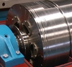
Rotating Assembly:-
The rotating assembly includes Bowl, Conveyor & Gear Box as shown in fig. 10. Machine is design so that flow will be countercurrent (solid & liquid travel in opposite directions axially in separating zone and discharge at opposite ends). The fluid is feed through inlet tube using pumping device. This fluid contains mixture of two different densities liquid and suspended solid particles (micron size). The fluid is passing through conveyor which have feed zone. The centrifugal force is created at the feed zone of the conveyor due to rotational movement of the conveyor which throws away the fluid in the gap between conveyor and bowl. The bowl and conveyor are rotate with same direction but different speed due to which the higher density suspended particles are collected at the inner surface of bowl and the less density liquid create pond in between bowl and conveyor. The conveyor has tapper part at one end which helps to remove the saturated cake solids at drive end. The liquid is traveling towards to non-drive end by using moon type plate (small moon type outlets at bowl bigger end using the taper section in other end of bowl. The speed different control between bowl & Conveyor by two or three stage planetary gearbox, but if required variable speed between bowl and conveyor as per process requirement so that speed control by using back-drive system. Separated solids can vary from a dry powder to a paste. & the torque of the total assembly is controlled by torque controller as per set points of gearbox overall torque. In failure in torque controller by disconnecting total assembly. Hubs from bowl and conveyor assembly at both end are rested on frame using bearing housings which have ball or roller bearing to resist axial trust of conveyor.
Modified feed zone
The fluid has very high axial velocity when it passes through inlet tube f. The conveyor rotating motion and axial flow create unavoidable splashing. There is obstacle created at the inlet zone which breaks fluid flow uniform decrease in velocity creates laminar flow. The inlet zone accelerates the feed slurry up to the speed of the bowl. A properly designed inlet zone keeps any degradation of the feed solids to a minimum as well as avoiding disturbance of the sediment in the bowl.
Base Frame Assembly:-
The static and dynamic load of machine is high so to sustain that there is use of base frame. The rotating assembly is covered with guard.
Liquid Discharge Section
In a two-phase decanter, the liquid level is regulated by dam plates. When operating in a three-phase mode, each phase discharges over a set of dam plates into separate baffled compartments in the casing. In certain applications, a centripetal pump discharge that utilizes the pressure head developed by the rotating liquid phase is used to pump the liquid from the decanter.
Decanter centrifuge offers a wide range of wear protection to meet the requirements of the many different applications in which centrifuges are installed:
- Welded hard facing or spray coating
- Ceramic
- Tungsten carbide tiles
- Chilled hard metal port castings
- Plastic liners
In order to minimize maintenance costs for applications involving highly abrasive products, all wear protection elements, except welded hard facings or spray coatings, are field replaceable.
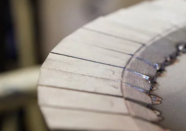
1. Wear Protection Hard-Surfacing Conveyor
2. Wear Protection Tiled Conveyor
Most decanter centrifuge comes with moon types of plate dam, but some of the application decanter centrifuges have pressurized discharge of the liquid phase by use of a paring disc, or centripetal pump. The clarified liquid enters the paring chamber. The stationary paring disc which has channels for the liquid is immersed in the rotating liquid. This causes a pressure differential and the liquid is forced through the channels converting the energy of rotation into a pressure head sufficient to pump the liquid out of the machine and to succeeding processing steps.
Decanter With dam plate
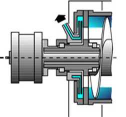
Decanter with paring Disc
Decanter with Centripetal pump
By applying back pressure to the paring disc outlet, it is possible to minimize or even eliminate air (oxygen) pick-up and foaming.
Paring discs may also be made as so-called friction (or vaneless) paring discs.
Instead of channels the paring disc consists of two discs at a small distance, 2 to 4 mm. This type of paring disc is softer to the liquid, but has lower capacity and higher power consumption than the type with channels.

Solid Discharge Section
Depending on the application, the consistency of the configuration of the discharge zone is therefore chosen to enable such “cakes” to exit as effectively as possible. Hard surfacing technology combined design enables erosion-prone components used in the solids discharge zone to be replaced on site at low cost and with a minimum of disturbance to production.
Scroll and Differential with Speed Control System, over load Protection & Remote Control
If a disruption in the system develops, an integrated two stage overload protection offers excellent security against clogging of the machine: If the increase in differential speed is not sufficient to compensate for a solids overload, the feed supply is stopped until the torque falls back below the set point. In the majority of situations, this is sufficient to remedy the overload without having to shut down the system. If this step is insufficient to keep the scroll torque from rising, the bowl drive is shut down when the torque reaches the second higher set point. As the bowl speed decreases, the torque is reduced and the machine will usually empty itself. Typically, there is no need to manually remove the solids. Machines with a hydraulic drive allow for solids discharge at full scroll torque even when the bowl is shut down.
 Fluctuations in the solid concentration and throughput may cause a decrease in separation results, a machine blockage, or an overload of the centrifuge. To avoid problems and to fully utilize the capacity of the centrifuge, the differential speed needs to be continuously monitored and adjusted to the operating conditions. It offers control systems for the differential speed which are based on the following principle
1) The scroll torque is an indicator of the bowl solids load.
2) The load, and therefore the torque, should be kept at an optimum value.
If the torque exceeds the optimum value, the control system increases the differential speed to more quickly convey the solids out of the bowl until the torque decreases. Conversely, the differential speed is reduced when the torque decreases. This automatic control process ensures optimum separation during normal operation.
Purging Hazardous Material
If centrifuges are used to process products whose vapors together with oxygen may form a flammable suspension, any risk of explosion must be avoided by substituting air with inert gas. Generally, nitrogen is used. Centrifuges and system components used for the processing of hazardous materials have to be gastight to prevent the exit of vapors into the atmosphere as well as to avoid the entry of air into the system. Typical examples are processes in the chemical, petroleum, and pharmaceutical industries, or processes with flammable organic solvents or those involving oil sludge treatment. These centrifuges comply with ATEX 95 in Zone 1 or Class 1, division 1, up to temperature class T3.
Before starting, the entire system, including the centrifuge, is purged. In order to do this, large volumes of inert gas are flushed through the system until the amount of oxygen is reduced to a non-critical and safe level. Purging is complete if the amount of inert gas delivered to the system reaches a multiple of the system volume, or if an oxygen probe at the centrifuge housing shows a safe oxygen concentration.
Blanketing
After successful purging and during operation with the product, sufficient inert gas is fed into the system to ensure a small overpressure. This prevents atmospheric air from penetrating into the system.
Control of Centrifuge Purging with Inert Gas
This accomplished with a differential pressure monitoring system with integrated automatic control. Thus, a fixed overpressure in the sealing system is constantly maintained using control valves. Manual readjustment is not required anymore. This method ensures a small overpressure within the sealing system and the inside of the centrifuge guaranteeing protection against air leakage into the system and product emission into the atmosphere.
Processing of Materials Susceptible to Oxidation
In particular, processing beverages and food requires that the product is prevented from undergoing oxidation. For this purpose, the leakage of air into the centrifuge is prevented with relevant design features and the centrifuge is purged with inert gas. In many cases, carbon dioxide is used as inert gas. A system monitoring the flow of gas is commonly used.
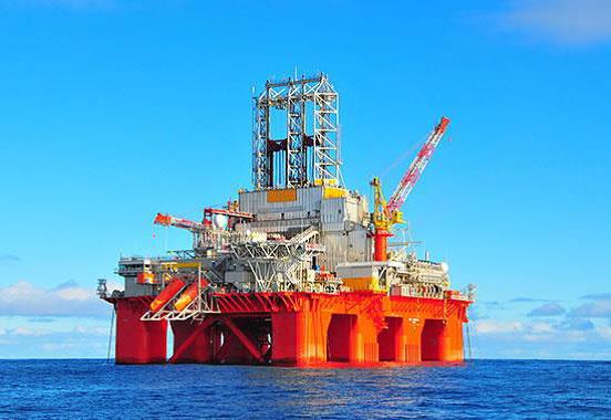
The motivation for processing drilling mud, drilling emulsions, and drilling fluids is easy to understand: on oil platforms, in tunneling, or in other industrial sectors where drilling systems are applied, continuous cleaning of these liquids is crucial in order to guarantee and enhance the optimum processing of the drilling systems. Furthermore, constraints and requirements regarding the environment (pollution of groundwater and seawater) are getting stricter, requiring continuous treatment and separation of drilling mud, fluids, and emulsions.
 Drilling mud has to fulfill multiple functions: It has to lubricate and cool the drill head and carry the bits of rock and detritus away which are cut off. Drilling muds are based on water, oil, or polymer along with various additives such as stabilizers, flocculants, corrosion inhibitors, defoamers, surfactants, detergents, lubricants, and more. Modern drilling systems form a closed cycle from which no solids are able to escape. As a result, any particle which gets into the closed system has to be separated. Shaking screens and hydrocyclones can separate out coarse particles, but a G-Centri-Force Decanter separates small and fine particles. For a better overview and understanding of how drilling mud, fluids and emulsions are separated and processed using a G-Centri-Force Decanter, please have a look at the process scheme below.
G-Centri-Force DG series drilling mud decanter centrifuges are designed specifically to remove unwanted solids and fine particles from virtually all kinds of used drilling mud, including those based on water/synthetics and conventional oil-based drilling fluids.
Built for heavy-duty processing, a DG installation handles large quantities of solids in the feed flow, as well as being able to cope with coarse, abrasive particles. It also efficiently removes the vast majority of fine particles, down to sizes of around 5 microns. Traditional equipment is unable to deal with these particles, which have a serious impact on the quality of drilling mud because of their abrasive effect. The G-Centri-Force DG series decanters have been designed for the best available wear protection in the market.
G-CENTRI-FORCE CENTRIFUGES FOR PROCESSING DRILLING MUD, DRILLING EMULSIONS, AND DRILLING FLUIDS
G-CENTRI-FORCE CENTRIFUGES FOR PROCESSING HAZARD REFINERY CRUD OIL TANK BOTTOM
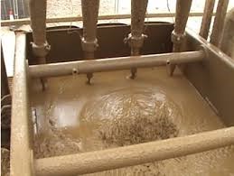
LAGOON CLEANING
A DG installation can pave the way to dramatic reductions in drilling mud costs because less mud is wasted. Being able to remove solids in very dry form also means lower costs for transporting and disposing of solids waste. Additional savings stem from opportunities for automatic, unattended operation, and from the extended service life of DG installations due to their exceptional reliability. The machines have been designed for reduced power consumption in relation with process flow.
Optional modules are available to match DG set-ups to specific needs encountered on drilling rigs. These include both fully automated modules and relatively simple manually operated modules that together provide cost-effective solutions to all solid’s separation requirements.
Drive System
A decanter centrifuge requires two independent drive systems. The bowl operates at a high rotational speed to create a high g-force. The scroll rotates inside the bowl with a low speed to the bowl (differential speed). G-CENTRI-FORCE applies advanced engineering techniques to accelerate the decanters to high speeds in safe. One of the most important key factors for decanters is the differential speed. Differential speed determines the amount of moisture held in the separated solids and the clarity of the Central. This speed can be adjusted according to the required product characteristics. Drive systems which run to determine this speed are given as below:
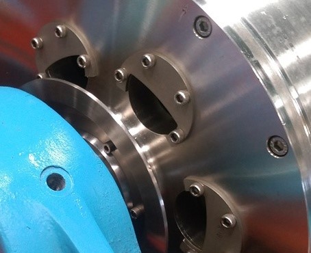
1.Constant Speed Drive System (fix speed with torque arm)
This technology is developed for applications requiring solid-liquid separation. Separating one mixture with one liquid and one solid with different density in single equipment has simplified. Two-Phase Decanter centrifuges have been operating according to the same basic principle since the 19th Century. The sun-wheel shaft is immobilized by a spring-loaded lever (fix speed with torque arm) resting against a buffer on an operating arm. The arm is fixed on a shaft, the other end of which carries the switching lever. In the operative position, this lever is pressed against the upper abutment pin by the compression spring. Increased load on the conveyor will increase the pressure exerted by the small sun-wheel lever on the buffer of the operating arm. If the load is high enough, the switching lever will rock over against the lower abutment sun-wheel pin. This movement releases the switch. The sun-wheel lever can now rotate freely with the gearbox, corresponding to zero conveying speed. The action of the switching lever also shuts down the main drive motor and the feed pump and actuates an alarm signal.
2. Countershaft transmission by G-Centri-Force
The gearboxes an intermediate shaft (layshaft) is driven from the sun-wheel by use of a belt. Power is transmitted back to the bowl by use of another belt. With this system, it is possible to select a variety of differential speeds by changing pulleys and a Share pin/GS coupling protects the decanter against torque overload. They also benefit from the ability to permit some change in the choice of differential by appropriate change of pulley sizes.

3. Back-drive with AC motor with using VFD
This system is a variant of the AC motor back drive system. The AC motor, equipped with a braking device, facilitates five differential speeds - two by breaking the sun-wheel shaft, two driving the pinion shaft, and one with fixed sun-wheel. This system is widely used in the oil field application. A fully regenerative system developed by us is available. The sun-wheel motor is connected to a frequency converter whereby the differential speed can be changed. A second frequency converter is connected to the first one by use of a DC bus whereby it is possible to put the braking power back to the grid when the sun-wheel runs in the same direction as the bowl. Even if the main motor is connected to a frequency converter two dedicated frequency converters for the back-drive are used. The system is controlled by use of the G-Centri-Force PLC System.

3.Hydraulic back-drive
The main components of the system are a hydraulic pump with a variable displacement volume and a pump with a fixed displacement volume. A decanter centrifuge requires two independent drive systems. The bowl operates at a high rotational speed to create a high g-force. The scroll rotates inside the bowl with a low speed to the bowl (differential speed).
The scroll and bowl drive of the hydrostatic drive system operates independently from one another in terms of energy and control technology. Torque and differential speed can be controlled according to load and pressure relation. The drives can be directly and infinitely variably controlled, which allows ongoing adaptation to the separating tasks. The fixed displacement pump is connected to the sun-wheel shaft of the gearbox. Thus, the speed of the sun-wheel shaft depends on the oil flow through the pump. The sun-wheel shaft is made to rotate at a certain speed by the oil flow from the fixed displacement pump. When rotating in the same direction as the bowl the sun-wheel shaft is braked and power is either transmitted back to the bowl via the variable displacement pump and the V-belts, which in that case works as a generator.
A small feed pump mounted on the variable displacement pump provides continuous circulation of oil between the closed circuit and the oil tank. This ensures cooling of the system and constant minimum pressure. Overload protection is on three levels. If the decanter cannot scroll itself free by automatically increasing the differential speed, two pressure switches and a relief valve placed in a valve block make sure that:
• The feed pump is switched off when the torque reaches a pre-set level.
• The decanter is stopped if the torque increases further above the pre-set value.
• The relief valve makes sure the pressure cannot damage the system.

4.Eddy current back-drive (ECB)
The Decanter centrifuge consists of a bowl which rotates at high speed and inner screw conveyor which rotates in the same direction but at a lower speed. Wide ranges of slurries can be treated by varying the relative speed of the bowl and the conveyor. An eddy current brake-drive can be used to vary the differential speed by breaking the sun-wheel shaft. The brake can be mounted in line with the gearbox or to the side or below the gearbox and be connected to it with belts and pulleys. The braking torque depends on the magnetic flux which in turn depends on the current in the field coil. By changing the current the speed of the brake can be changed and thereby the differential speed.
The current is controlled by a controller, an ABC (Automatic Back drive Controller) or a VS (Variable Speed). The ABC or VS displays information about set points, main speed, differential speed, and torque. The differential speed can either be pre-set to a constant value, or it may be allowed to vary by keeping the torque on the sun-wheel shaft constant. As the name suggests, the ECB can only brake the sun-wheel shaft. The maximum differential speed of the conveyor is therefore limited by the bowl speed, the gearbox ratio and the minimum allowable speed of the ECB.
PLC Control Package
Each G-355 decanter centrifuge is equipped with a PLC control package as standard, pre-installed and Factory tested. The combination of PLC control systems and G-355 separation technology makes sure you get the most out of any G-355 installation, at the same time as keeping costs for installation, commissioning, operation and maintenance to a minimum. Additional enhancement packages are available for the PLC controls package.


GCF-PLC control system
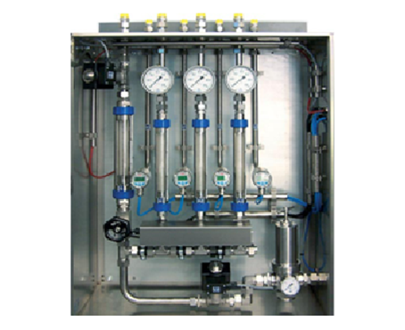
Decanter With Skid
GCF provide decanter with skid including screw conveyor for sludge handling, feed pump for inlet flow, Flow control value with flow meter for controlling the inlet flow, High- & low-level indication for light phase tank with light phase pump system as per additional cost.

Decanter With Skid

Advantages Of Modern Decanter Centrifuges
Modern Decanter centrifuges have many advantages in comparison to other separation processes such as filtration and static settling. Active one movement more differential speed using three stage gearboxes. Due to Conveyor Partition plate between solids & liquids during solid-liquid separation; active more solids dryness.
Drawbacks Of Conventional Technology In G-Centri-Force Decanter Centrifuges
1. There is use of bolted parts at the feed zone which required to reconditioning after some time.
2. Conventional system required additional chamber to reduce the impact velocity.
3. Sharp edges increase the erosion problem and reduce the life of feed zone.
4. Three stage gearbox systems reduce the conveyor load during operation & active higher definitional speed in single direction of rotating.
5. Conveyor Partition plate between solids & liquids during process; active more solids dryness.
6. Auto 24x7 greasing system; save the time & money
7. Temperature & Vibration sensors; observe bearing temperatures & machine vibration during running the decanter centrifuge.